Appearence Lost While Importing Revit Family to Architecture
Consign to DWG

Objectives
- Empathise the customized settings before exporting to DWG.
- Be able to create a useful "Export Setup"
Prerequisites
- User has bones skills in BIM modelling with Revit Software, and understands the language used.
- User has basic skills in Autocad formats.
Description
DWG export consists in making a translation of Revit sheets/views to CAD formats, which are radically different.
When working with BIM models, the platonic state of affairs is that there is no demand to export to DWG, and all stakeholders are able to swallow the BIM model.
But this is just an platonic world. Actually, it is required in many cases to export to CAD formats.
This guide explains the general procedures and settings to control such process.
Procedure
Export to DWG is done from the Menu>Consign>CAD Formats>DWG.
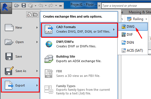
From this window, two actions are performed:
- Select views/sheets to export.
- Select consign configuration that will be used.
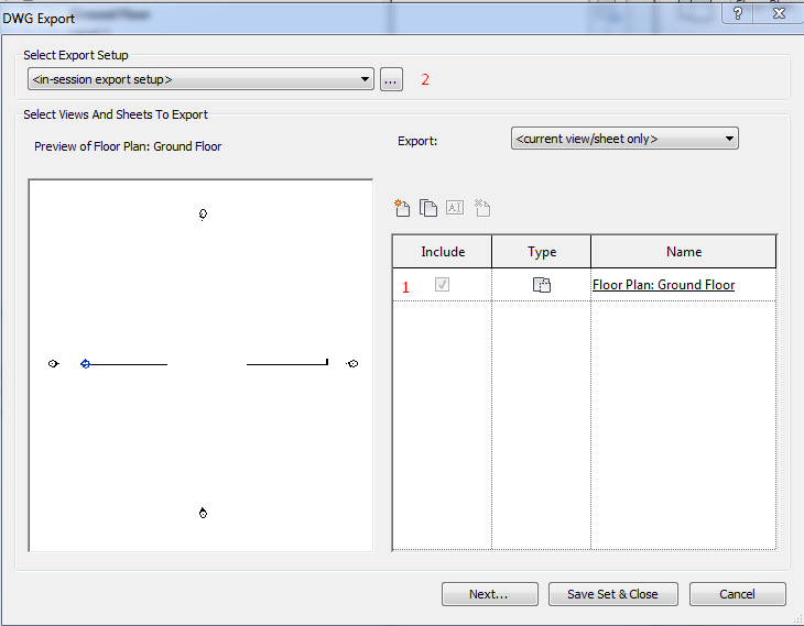
Export settings menu
Select elements to exist exported
You tin export to DWG both views and sheets.
Views properties
The views are exported to space model.
3D axonometric views are exported to a 3D DWG in the infinite model.
Sheets backdrop
They are exported to paper space. The content of the graphic windows are exported to model space.
Select views/sheets to export
From the drib-down Export menu we have two options:
- Current view/sheet only: this option simply export the view that is active at that moment.
- In session view/sail set: this option you can choose between views and existing sheets.
In whatever case the selection of views and sheets can be recorded to be used later.

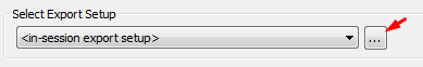
Export Setup
Export Setup Button is located at the top left (information technology is also reachable direct from the Export>Options> Export Setups DWG/DXF).
From the driblet-down menu you tin select a specific configuration.
Different export configurations are listed considering previously they were directly saved in the file, or transferred from other projection files through the tool "Transfer Single" or "Transfer projection standards".
It is recommended to record the performed settings. The configuration is saved as an internal project standard of Revit.

In the export settings window, we tin can find the post-obit tabs:
- Layers
- Lines
- Patterns
- Text Fonts
- Colors
- Solids
- Units Coordinates
- Full general
Consign settings
General
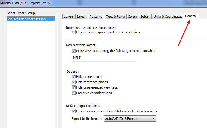
Consign of Rooms , Spaces and Area Boundaries equally closed polylines. It is recommended not to select it unless they are specifically useful in the DWG file.
- Surface area polylines are generated from area plan views only.
- Room polylines are generated from flooring plan views or ceiling plan views only.
- For Revit MEP, this pick also applies to spaces.
For rooms, the exported polylines match the boundaries of rooms in Revit. The room boundaries are exported onto a single layer, and that layer is turned off by default in the DWG file. The polylines include the following XDATA information for room boundaries:
- Proper name
- Number
- Occupancy
- Occupant
- Department
- Comments
For areas, the polylines include the post-obit information for area boundaries:
- Name
- Comments
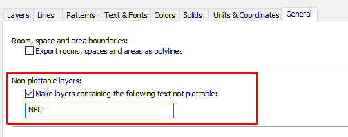
Configure non-printing layers . This is a very useful choice when you want to export sure elements that should not be printed in AutoCAD, if this option is enabled, layers will exist defined in AutoCAD every bit non-printing. Select the Make layers containing the following text not plottable option to mark as non-plottable any layers whose names contain the specified text.

Options: Click whatsoever of them to refine the export customization:
- Hide Scope boxes: Select this option to hide scope boxes in the exported file.
- Hibernate Reference plans: Select this selection to hide reference planes in the exported file.
- Unreferenced view tags: if you have a section simply it is not placed in any sheet, its symbol will non exist exported.

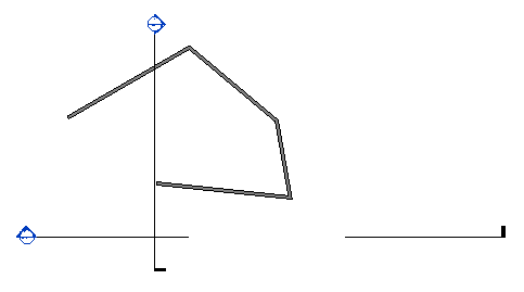
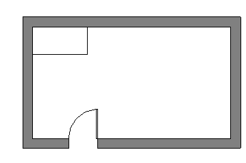
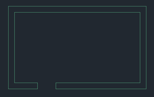
- Preserve coincident lines: Select this option to overlap coincident lines in the exported file.
When you export the model to DWG, by default the coincident lines are non preserved. That is, if you brandish but the wall layer, the export data does not include the lines that are coincident with the other elements:


Set the export views and links equally xref. Articulate this check box if yous desire whatever Revit or DWG links in the project to be exported to a single file rather than to several files that reference each other.
Set the version of the DWG file. Choose the correct Autocad version that is compatible with the installed software in guild to be able to open the exported drawings.
Units and coordinates
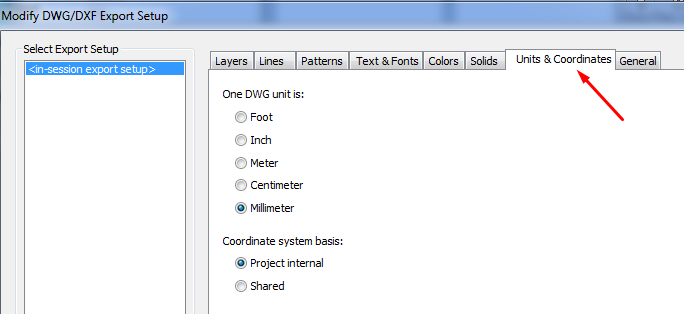
The resulting DWG file units: Choose the units of the exported file. Go on in mind that when we export a sail, units will be the same for model space and newspaper space.
For regal projects, the default unit is inches. For metric projects, the default unit is meters.
The system of coordinates:
- Internal project. The internal origin point is used as origin point in AutoCAD when exporting with Internal coordinates selection.
- Shared coordinates. The survey signal is used as origin point in AutoCAD when exporting with the Shared coordinates choice.
Solids
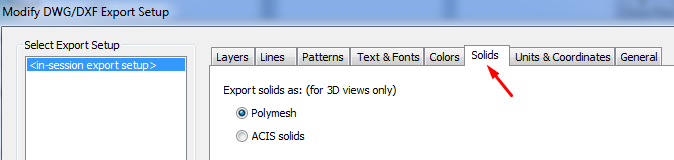
Polymesh: Exports all visible Revit geometry as polymeshes. A polymesh is a 3D shape consisting of multiple polygons that are meshed (joined) together. This geometry is referred to as face up-based.
ACIS solids: ACIS is a solid modeling technology. Any elements that are already polymeshes (such as toposurfaces and import symbols that contain polymeshes) remain as polymeshes.
Colors

Index colour (255 Colors). For colors that are set by category, the indexed colors specified on the Layers tab of the Modify DWG Export Setup dialog will exist used.
When colors are non fix past category (if elements in views are overriden past whatsoever mean -filters, past element, etc.-) and the override is preserved in the export, Revit uses the closest match from the 255 indexed colors and thus may not provide an exact match for RGB and Pantone colors.
Truthful color (RGB Values). Uses the RGB value from Revit, rather than the indexed colour from the Layers tab of the Modify DWG Export Setup dialog.
Sometimes it may be practical to use this option, since the appearance in terms of colours and line weights that takes the DWG (with regard to press) is the same every bit in Revit, without the demand for a CTB file that makes the colors transformation.
If you are exporting a view that contains a linked project, the link is treated as an override. To ensure that colors and other graphic display settings are preserved in the exported file, on the Modify DWG Export Setup dialog (Layers tab), select "Export all properties BYLAYER, merely exercise non export overrides."
Text & Fonts
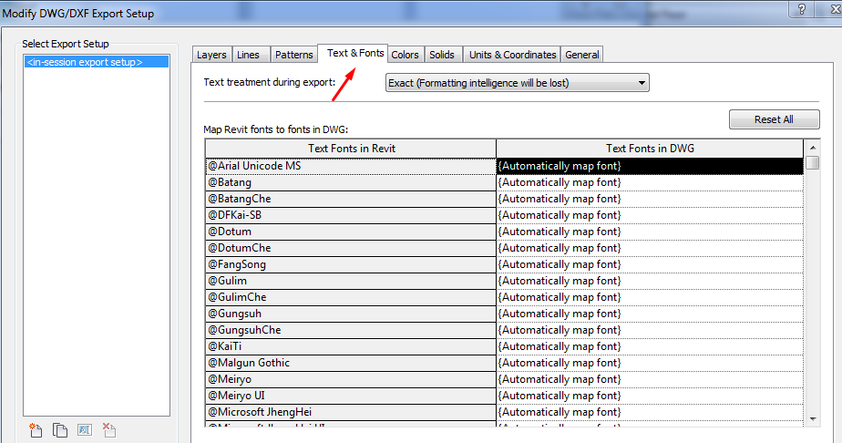
Preserve visual fidelity (Formatting intelligence volition exist lost). Exported text volition look exactly every bit it does in Revit (exact line wrapping). However, if the text includes bulleted or numbered lists, that paragraph functionality is lost upon export. Pressing Enter within a formatted paragraph volition not restore the formatting.
Preserve editability (Formatting intelligence will be maintained). If exported text includes bulleted or numbered lists, that paragraph functionality is maintained when the text is edited. Pressing Enter inside a formatted paragraph volition restore the formatting. However, the visual appearance of the text may vary from the original, whether or not the note contains a list (that is, wrapping may vary).
Mapping Revit Text Fonts. By default, all Revit fonts listed in the mapping table have a value of "Automatically map font" in the Text Fonts in DWG column, which means the Revit font will exist maintained in the exported file. If you desire to map a Revit font to a specific DWG text font, click the value for that font in the Text Fonts in DWG cavalcade, so select the desired font from the drop-down list.
It is recommended to apply this default option, unless it is necessary to apply specific Fonts in DWG unlike to those used in the model to be exported.
Patterns
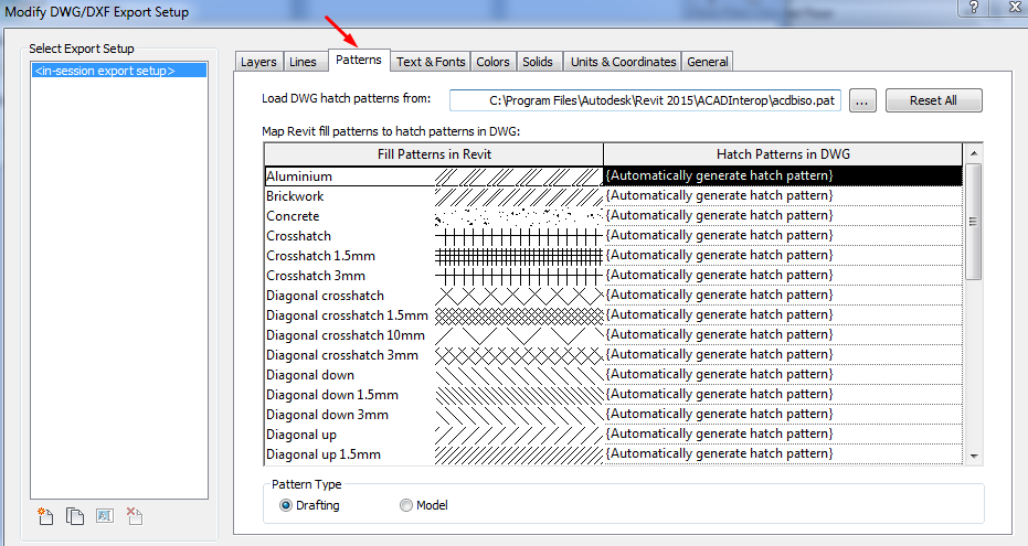
There is a relationship between the "Patterns" used in Revit and the "Patterns" used in DWG applied when exporting.
By default, if the selected option is "Automatically generate hatch pattern". The "patterns" of Revit volition export exactly and so Autocad will automatically create a new "design".
Yet Revit also gives the option to select a "pattern" of existing Autocad to a "pattern" of Revit. So previously you must select from the top menu the .pat file to be used.
In both cases yous can select Blueprint Blazon equally:
- Drafting. The scale remains fixed, regardless of the view scale.
- Model. The scale of the hatch is fixed regarding the model. Information technology changes co-ordinate to the view scale.
Lines
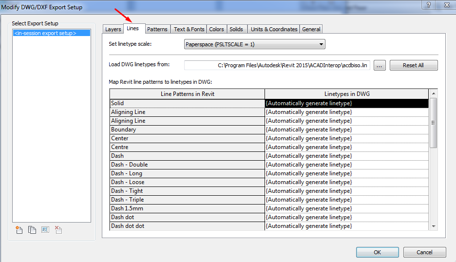
The process in Lines is the same as patterns. In this example the extension it is required is a .lin to map the line types.
At the top of the window, you tin likewise select "Linetype Scale" to command the scale to which line types are exported. The options are:
Scaled Linetype definitions. This option preserves graphical intent by exporting linetypes the same as they were previously scaled by view scale.
Modelspace (PSLTSCALE = 0). This option sets the LTSCALE parameter to view calibration and the PSLTSCALE to 0.
Paperspace (PSLTSCALE = 1). This selection sets the value of both LTSCALE and PSLTSCALE to 1. Revit LT linetype definitions are scaled to reverberate project units, but otherwise they are exported as is.
Layers
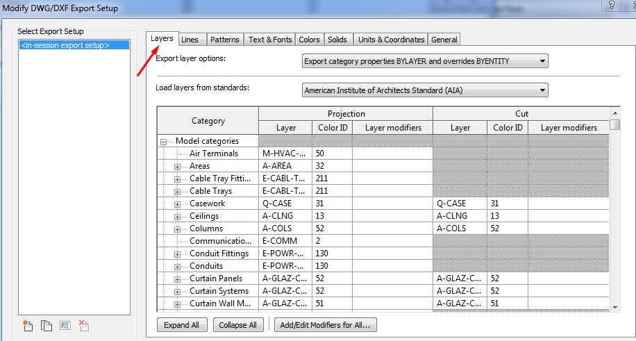
Information technology configures the export from Revit objects (classified by categories and subcategories) to layers of Autocad.
The schedule shows: on the left the list of all categories of Revit, and on the right DWG layers in which graphical representation of these categories will be placed. Distinction is made between layers for graphic representation in project and section. There is a column non only for the layers proper name only for the color likewise "Color ID".
In the offset drop-down bill of fare y'all tin can cull betwixt these options:
Consign category properties BYLAYER and overrides BYENTITY. A Revit element with view-specific graphic overrides will retain those overrides in the CAD application, but will reside on the same CAD layer equally other entities in the same Revit category.
Export all properties BYLAYER, but do not export overrides. View-specific graphic overrides will be ignored in the CAD application. Any exported Revit element volition reside on the same CAD layer as other entities in the same Revit category. By forcing all entities to brandish the visual backdrop divers by their layer, this option results in a lower number of layers and provides by-layer command over the exported DWG file.
Export all properties BYLAYER, and create new layers for overrides. A Revit element with view-specific graphics will exist placed on its own CAD layer. This option provides past-layer control over the exported DWG file, and preserves graphical intent. Nevertheless, it increases the number of layers in the exported DWG file.
In the second drop-down menu in a higher place the box you can select a defined configuration of layers according to unlike standards.
Best Practices
Limit Geometry
In Revit, a view of the building model contains many objects and a lot of data. When exporting a model for use in another software awarding, Revit exports only the objects that are visible in the views. Past reducing the amount of model geometry (and its underlying data) that is exported, yous tin achieve the following:
- Improve operation of the export process.
- Reduce the size of the exported file.
- Amend performance of the importing application.
- Reduce ataxia (not-essential items) in the exported file, and hence the amount of piece of work required to delete these objects from the file in the importing awarding.
Techniques to reduce the corporeality of geometry to be exported.
- Turn off visibility of graphics that you don't demand for your specific purpose.
- If you hide elements temporarily, Revit will ask yous if y'all desire preserve this situation while exporting.
- Apply a section box or a crop region to define a specific region.
- Specify the detail level.
- Call back that Revit export exactly what you see.
Adapt scale
Adjust the view scale to command the precision/performance ratio.
When you export to 2d DWG, you export a scaled 2D view of the model. The view calibration you apply determines whether the resulting view is exported for precision or for performance. For example, if your model contains 2 lines that are 1mm apart and the view scale is 100, the lines will exist considered to be within tolerance, and the exported DWG will contain a single line (exported for operation). If the view scale is twenty, the exported DWG will comprise separate lines (exported for precision).
Tips&Tricks
If a hatch pattern is not visible in the exported DWG file, and the message "Hatch Pattern Too Dense" displays in the AutoCAD text window, effort adjusting the AutoCAD system variable HPMAXLINES to increase the maximum number of hatch lines that are generated in a hatch performance.
If a hatch pattern is not exported to a DWG file, check if the pattern (or cloth) has transparency applied.
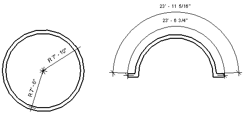
Revit always tries to map the Revit dimension parameters to the proper DWG Dimension styles properties. But in some cases there may be parameters that cannot exist mapped. At that point Revit will export the dimension to preserve its visual fidelity. The visual fidelity will only be a temporary display, as soon as the dimension is regenerated it will read its properties from the dimension style and the display may change.
| Case | Display in Revit | Display in AutoCad |
| Dimension Extension The brandish of a dimension extension is changed for a radial and an arc length dimension. | | |

When you export a 3D view to a DWG file, colors are treated as follows:
- Edge colors: because they are not rendered in AutoCAD, edge colors are ignored on export. This volition event in correct shaded/realistic views (edge overrides will no longer exist assigned to the entire model).
- Stage colors: color overrides on solid fills are supported on export, simply color overrides on patterns are not.
If you lot use one of the consign tools for a 3D view, Revit exports the actual 3D model, not a 2nd representation of the model. To export a 2nd representation of the 3D model, add the 3D view to a canvas and export the sheet view. Y'all can then open up a 2D version of the view in AutoCAD. It will be a vector drawing, not an image.
Call up that if you:
- Export views you can export either in internal coordinates or in shared coordinates.
- Export sheets you will only be able to export with the "Internal" coordinates pick.
Remember that the layer mapping settings that are configured in an english version of the software will not work with other language versions of the software, and vice versa.
As said, it'due south highly encouraged to:
- Customize the consign settings in accordance with your visitor standards is a chore that should exist done at least once. It takes time, just it can be used later on including it on the template or through "Transfer Single" or "Transfer Project Standards".
- Create or alter layer mapping to ensure that all information stored in Revit categories and subcategories will exist exported to the proper CAD layers (or levels, if exporting to DGN).
Determination
This guide explains how to manage and control the process of exporting .rvt views or sheets to .cad drawings. It makes a full general review of the setting options, and includes recommendations to lead this process according to the intended issue.
Source: https://www.modelical.com/en/gdocs/export-to-dwg/
0 Response to "Appearence Lost While Importing Revit Family to Architecture"
Postar um comentário